Core Technology
Unlocking quantum potential: Exploring the cutting-Edge of Cri/oFlex® cryogenic RF cable technology
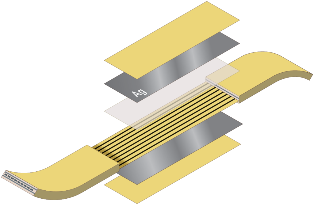
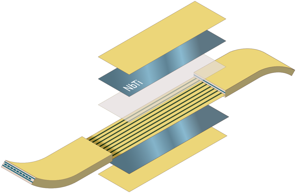
A stripline is a type of transmission line based on planar microwave circuitry. It typically consists of a conducting strip encapsulated in dielectric material and sandwiched between two conducting ground planes. Cri/oFlex® uses Polyimide [Kapton®] as a dielectric material as it remains flexible in cryogenic environments. Ag or NbTi are used as a conductive strip and ground layer. The standard product comes as a multichannel flex, with 8 channels per flex.
Materials
- Ag platform
- NbTi platform
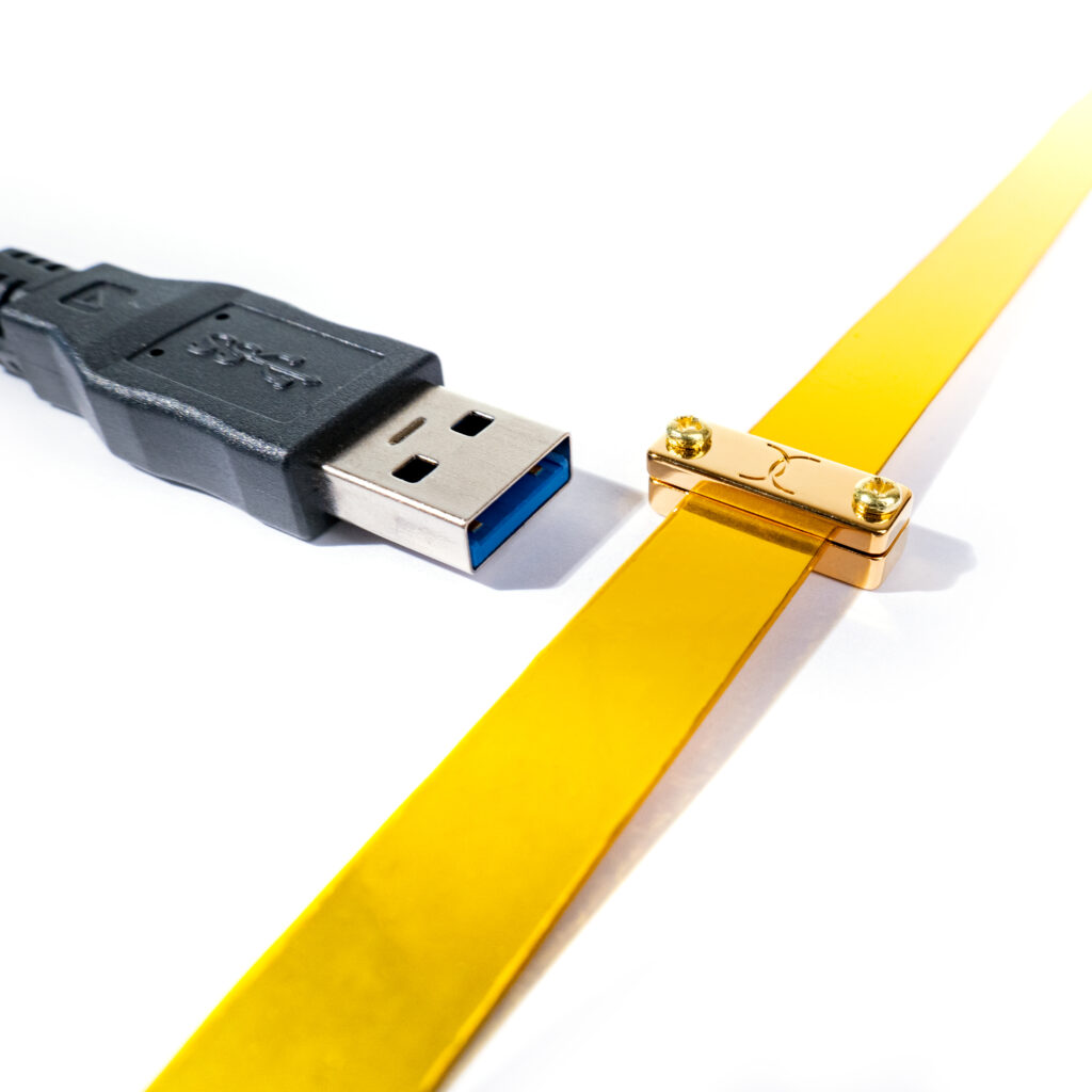
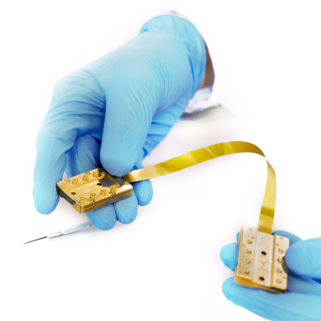
- Flexible and durable
Learn about our Ag and NbTi platform
Dimensions
- Ultra thin
- Length up to 100 cm
- Designed for cryostats
What size is Cri/oFlex?
Microwave performance
- S-parameters
- Crosstalk
- Impedance
What performance can I expect?
Thermal performance
- Heatloads
- Simulations
- Active/passive components
What thermal loads can I expect?
Materials
The typical Polyimide [Kapton®] layer thickness of a few tens of um is used as dielectric. Polyimide [Kapton®] is ideal material serving two purposes. First, it has great adhesive properties and allows to work with several metals. Second, its cryogenic compatibility and low thermal expansion coefficient makes Kapton® widely used for low temperature applications. The ground planes are made of the conducting or superconducting layers of metal depending on the functionality providing high frequency shielding.
Standard (Ag) platform
Cri/oFlex® workhorse material platform is silver (Ag). With the small cross-section it provides an optimal balance between low passive heat load and good transmission, well suited for temperatures that are too high for superconductors.
- Optimized balance between heat load and transmission
- Designed for cryogenics
- Economical option
Superconducting (NbTi) platform
Superconducting Cri/oFlex® based on NbTi. The superconducting stripline has two major advantages, the reduction of transmission loss and the reduction of the heat load. Superconducting materials not only have zero electrical resistance at temperatures below Tc but also close to zero heat conductivity. These cables are designed to handle up to several tens of milliamps of continuous current while superconducting. The critical temperature is around 9 K and the critical current over 150 mA.
- Only available superconducting flex in the world
- Designed for most stringent requirements
- Flexibel and durable
Dimensions
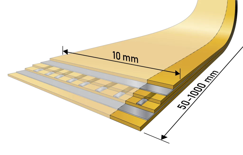
The conducting strips are being deposited and formed circuits on a shared dielectric layer. The complete in house production of Cri/oFlex® allows Delft Circuits to define and control all parameters of the thin films of the strips. These are thickness of the layer, width of each individual channel, pitch between channels. Standard Cri/oFlex® stripline contains 8 (eight) channels in one flex with a pitch from 0.1 to 1mm between channels. The width and thickness of the conducting layer can vary between a few nm to a few tens of um depending on the functional requirements. The length of the flexible section can vary between 5 – 100 cm. Extended lengths over one meter can be realized using Tabbi/™ interconnect.
- Length from 5 - 100 cm (extended lengths possible with Tabbi/™)
- Width up to 10 mm (for 8 channels)
- Thickness 0.3 mm
Microwave performance
Transmission is set by dielectric and resistive losses. The resistive losses are highly reduced at cryogenic temperatures and become negligible for superconducting Cri/oFlex®. The flex is designed for 50 Ohm impedance. Furthermore, the top and bottom ground planes are electrically connected using a network of vias to improve isolation between channels and ensure shielding from external sources of electrical interference.
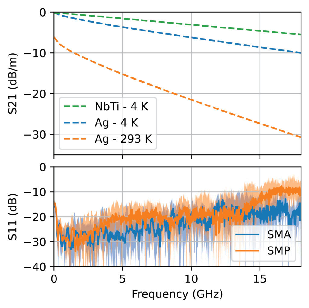
- S21 of Ag at 4K, the transmission losses at 10 GHz are 7 dB/m
- S21 of NbTi at 4K, the transmission losses at 6 GHz are 1.5 dB/m
A common concern for high-density microwave signaling is crosstalk. Our multichannel Cri/oFlex® 3 allows for high line density with good isolation. On the right, the near-end crosstalk (NEXT) and equal level far-end crosstalk (EL-FEXT) between channels in a room-temperature 20 cm long Ag Cri/oFlex® 3 with a 1 mm channel pitch are plotted. The solid line is the average of all channel combinations and the semitransparent area shows the best (furthest) and worst case (nearest channels) of an 8-channel flex. Even in the worst case, crosstalk is below -60 dB for signals up to 10 GHz. NbTi Cri/oFlex® has comparable performance.
Transmission properties
The transmission of Cri/oFlex® can be as low as 1.5 dB/m at 6 GHz for NbTi. For our Silver (Ag) platform a typical 6 dB/m at 6 GHz at low temperatures is normal. In the field these losses are denoted as insertion losses.
On the graph the Silver transmission is plotted for different temperatures.
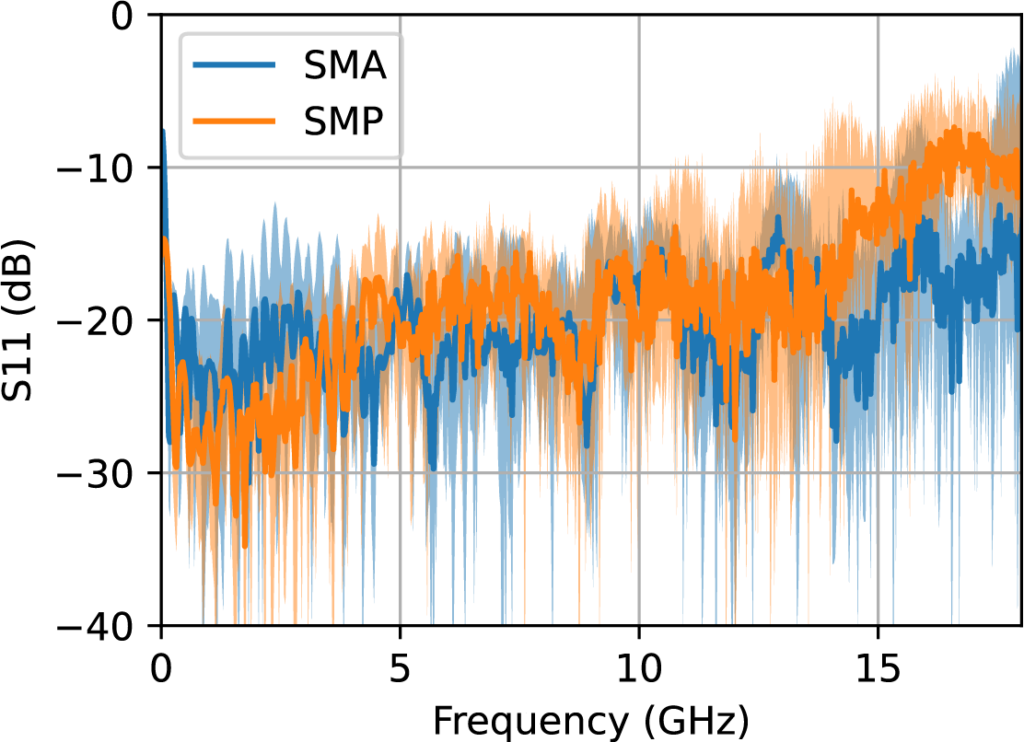
Below the transmission are the S11 reflections graphs shown. These are known in the field as reflection losses, as they appear as reflections for the system. The Cri/oFlex® is overall well below 15 dB for each reflection. For more information contact our engineering team.
Crosstalk
A common concern for high-density microwave signaling is crosstalk. Our multichannel Cri/oFlex® 3 allows for high line density with good isolation. On the right, the near-end crosstalk (NEXT) and equal level far-end crosstalk (EL-FEXT) between channels in a room-temperature 20 cm long Ag Cri/oFlex® 3 with a 1 mm channel pitch are plotted. The solid line is the average of all channel combinations and the semitransparent area shows the best (furthest) and worst case (nearest channels) of an 8-channel flex. Even in the worst case, crosstalk is below -60 dB for signals up to 10 GHz. NbTi Cri/oFlex® has comparable performance.
Thermal performance
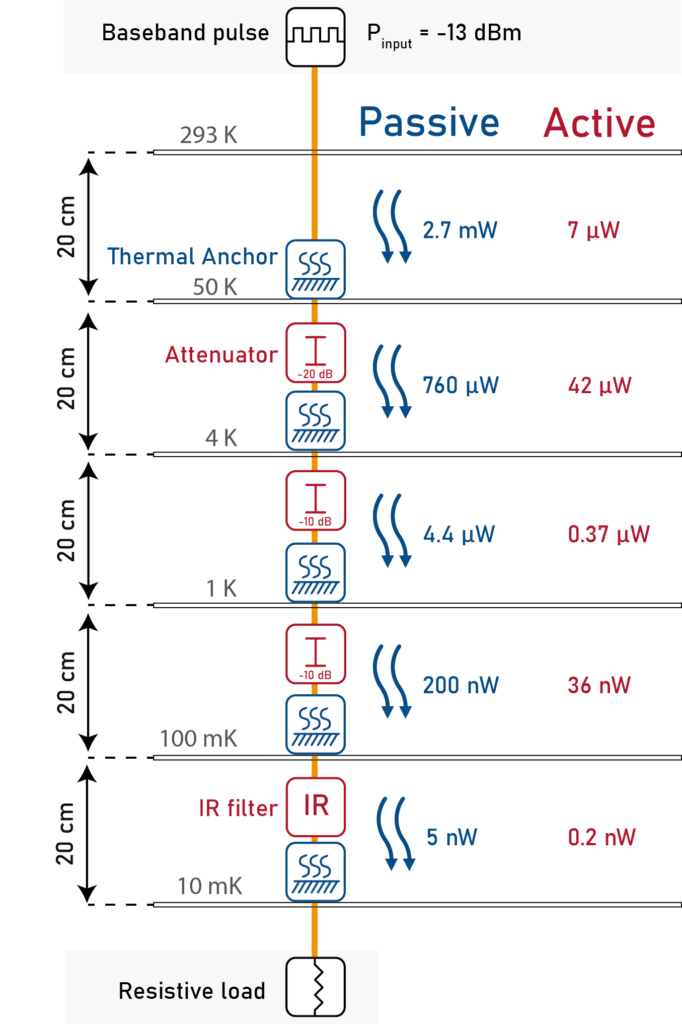
To account for the thermal properties of your cryogenic i/o, we have included thermal conduction models, as well as local heating models due to power dissipation. Given a specific temperature profile in a cryostat, we can model the expected temperatures of the Cri/oFlex®, and other components, as well as the expected heat load on each stage.
In the example Cri/oFlex® configuration shown, we display the simulated expected dissipative heat load for each segment between cryostat stages. The power dissipation from the baseband pulse generated by the room-temperature electronics depends heavily on the components and the signal power. In this example, the attenuator dissipates by far the most power, and should therefore be positioned at a location where the cryostat has sufficient cooling power. Performing these simulations allows our engineers to optimize a desired i/o chain to the customer’s needs.