Cri/oFlex® design guide
What functional requirements does your I/O chain involve?
The quantum computing I/O is a hardware module for connecting qubits in a cryogenic environment with control electronics at room temperature. It includes all I/O channels (input-output) needed for transporting downstream signals to qubits up to microwave frequencies and for returning upstream signals carrying their response.
The requirements of quantum computing cabling go far beyond a set of straight forward transmission lines, like coax cabling. For instance, it should not leak room temperature heat into the fridge down to the qubits, it should not inject room temperature thermal noise into the qubits, it should not leak gas into a vacuum environment nor produce outgassing, it should perform low-pass filtering up to the infra-red region, and it should offer additional thermal isolation to qubits via superconducting lines. To make this all happen, the i/o chains may incorporate components like attenuators, microwave filters, IR filters, superconducting sections, (travelling wave) amplifiers, and maybe even fiber-optic links. It also should have esdffective thermalization means to drain away residual heat leaking from room temperature, from signal dissipation (in attenuators) and from active components. Moreover, the footprint of each control highway module should comply with cryostat dimensions, and capable of connecting hundreds or thousands of qubits in a single cryostat.
The picture below illustrates an example implementation of how this may look like in practice.
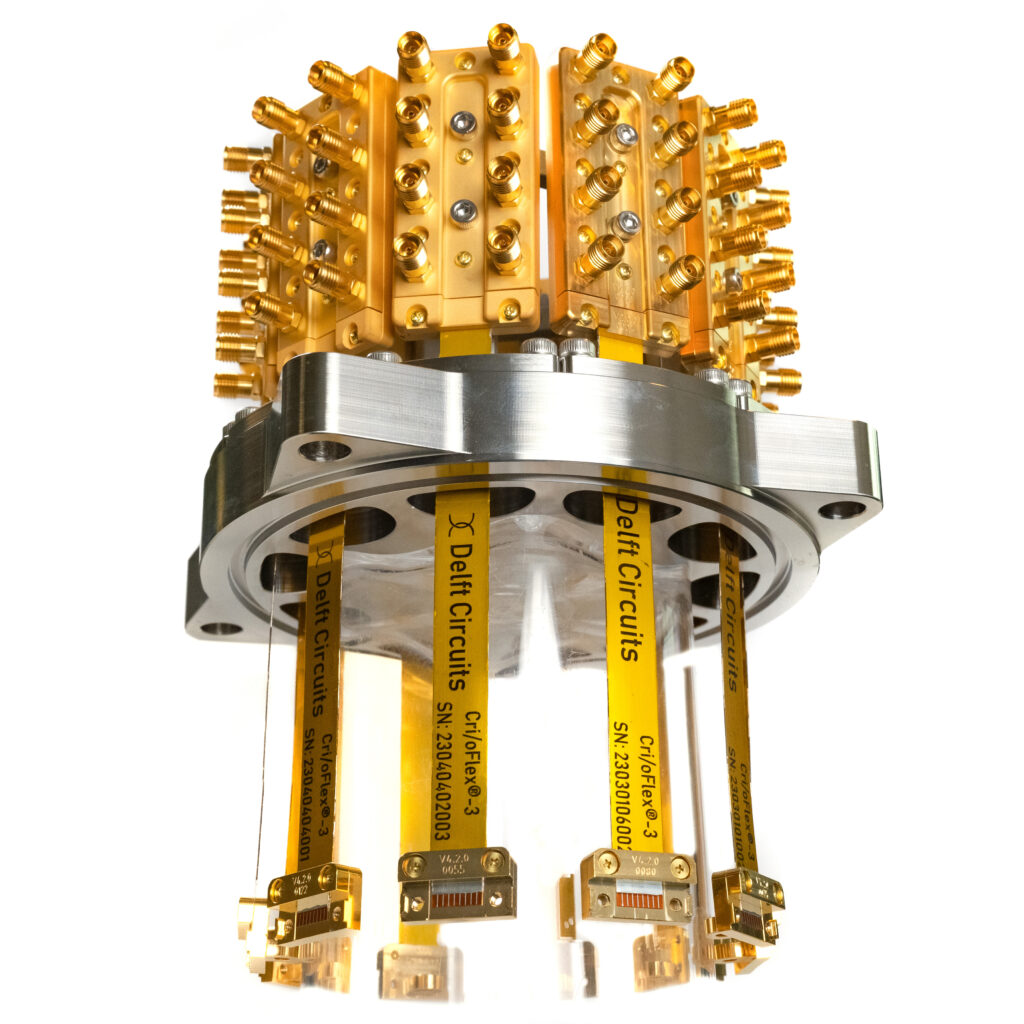
The picture above shows a possible room temperature node, at the head of quantum computing cabling module. This ring of connector blocks connects an I/O tree with 80 channels in a single module. Each block in this example, has 8 SMA connectors and feeds a very thin flexible stripline with 8 channels in a row. Each stripline enters the cryostat through its own vacuum feedthough and can be extended internally via dedicated Tabbi/TM stripline connectors.
These flexible striplines are small enough to be doubled through the same feed-through opening, allowing up to 160 channels.
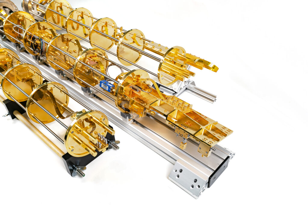
The picture above shows three examples of cylindrical modules that can be mounted inside a cryostat. They have several stages for thermalization via the cryostat. The room-temperature node is at the left side of the picture and has a ring with connector blocks. The milli-Kelvin node is at the right side where the quantum device(s) are to be connected. When needed, and enabled by the size of the cryostat, multiple of these modules can be mounted in the same cryostat, to control hundreds to thousands of qubits.
Functional description
The quantum computing cabling facilitates the transportation of downstream and upstream signals between control electronics, operating at room temperature, and quantum devices, operating at cryogenic temperatures.
The figure below shows example channels in a possible quantum computing cabling dedicated to a quantum computer using transmons. The I/O channels of spin-qubit quantum computers may be different, but this example alone may be sufficient to get basic understanding of various functional requirements for future standardisation.
In this example, the I/O of each qubit is handled via three downstream channels: one for microwave control signals, another one for flux control and a third one for read-out. The response signals of two or more qubits may share a common upstream read-out channel to reduce the overall number of channels. Travelling wave amplifiers may be used for amplifying these response signals and may need an extra TWPA pump channel for powering. As such, a 50 qubit transmon quantum computer may have 102 or more I/O channels.
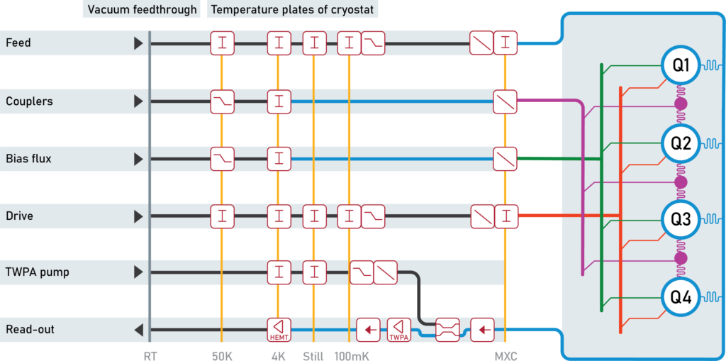
The involved I/O channels may be build-up from a chain of building blocks, for instance from transmission lines, attenuators, directional couplers, low-pass filters, infrared filters, DC-blocks, superconducting sections, amplifiers, isolators, circulators as well as thermalization means and vacuum feed troughs.
A design of a typical implementation usually starts with a functional diagram, including the length of each temperature stage, and position of desired components in each chain. Furthermore, realistic values for those functional requirements that are relevant for the application.
Functional requirements
The transmission requirements on the quantum computing cabling are to be defined in detail, and these requirements are highly dependent on the specific architecture and use case. The same applies to various interconnection and footprint requirements. But there are more issues of relevance that are to be specified, which may be less obvious. Their relevance is explained here as well.
Transmission requirements
Primary requirements on the transmission may include:
These are design values (target) as well as masks for upper and lower limits of the transmission in the desired passband of interest when the chain is terminated by a specified impedance. This could be offered for the full chain, as well for each stage and/or segment/component.
These are masks for upper limits on low-pass filtering for out-of-band frequencies. These masks may be specified up to one or two decades above the highest pass-band frequencies, to reduce out-of-band noise.
An effective reducing of out-of-band noise up to even infra-red frequencies might be of importance for qubits that are sensitive for it. For instance, if pulses are to be modulated on an 8 GHz carrier, these masks might be specified up to 100GHz or beyond. It is not obvious to achieve that with a low-pass microwave filter. This is because of the distributed nature of filters with transmission lines that have the fundamental limitation of passing signals above the break frequency. For instance, a 7th-order stripline filter up to 10 GHz, can have an out-of-band passband between 30 and 60 GHz.
Therefore, the use of a microwave filter with an additional “IR-filter” may be essential to be compliant with out-of-band specifications. Such IR-filters are usually based on transmission lines with very lossy dielectric materials (like metal-powder filters), which can offer an extra slope (expressed in dB/GHz) up to 100GHz or more.
These are requirements for DC-currents and low-frequency characteristics, for instance to separate bias currents from signals. When applicable, the maximum DC currents that may flow should be specified.
This requirement may become extra relevant when the current must flow through a super conducting section in the chain. Such section will lose its super conductivity when that DC current a critical current.
Another reason to specify a maximum current is dissipation in lossy elements (cabling, attenuators, etc). Dissipation may heat-up the channel and exceeds the cooling capacity of the cryostat.
These are requirements on step and/or impulse response of the full chain when the chain is terminated by a realistic impedance. This could involve rise-time, overshoot, and ringing. Note that when the line is terminated with an impedance of a quantum device that is quite different from 50 ohm, it may not be useful to specify response under 50-ohm conditions.
Reflection requirements
Reflections, due to mismatched elements, can cause rippling in transfer functions and distortion of pulses at the end of the chain. But this does not mean that the existence of reflections will always harm. Reflections against filters will always occur for stop-band frequencies, and the same applies for mismatched components. However, reflected pulses will quickly fade-away in lossy lines and will be fully absorbed in matched attenuators.
These lossy conditions are quite common in cryogenic chains. Therefore reflection requirements for individual components in the chain should not be over-specified if the impact of these reflections are hardly visible in the transmission properties of the full-chain.
What really matters is specifying limits to rippling in the transfer function and deformation of pulse and step responses of the full chain under realistic termination conditions. What occurs internally is hardly of any relevance.
Crosstalk requirements
Crosstalk between channels will cause that a pulse intended for one qubit, will also appear (in weakened form) at other qubits. One should distinct between two different measures of crosstalk: NEXT and EL-FEXT.
NEXT
Near End Crosstalk, between two channels is measured by injecting a signal into one side of a channel and observing the crosstalk at the same side in another channel. NEXT will then be the ratio between crosstalk and injected signal levels.
EL-FEXT
Equal-Level Far End Crosstalk, is measured by injecting a signal into one side of a channel and observing at the other side what signal level will arrive and what crosstalk will arrive in another channel. EL-FEXT will then be the ratio between arriving crosstalk and arriving signal.
EL-FEXT to the cold side of I/O channels is of primary relevance, due to the typical signal levels that occur in these I/O channels. If a pulse is injected to control a particular qubit, then the EL-FEXT may disturb the quantum state of other qubits. It also may result in a false response signal from qubits in general.
NEXT at the warm side of upstream channels is also if primary relevance for the same reason. The amplified response of a qubit in an upstream channel may still be very weak and can easily be disturbed by pulses injected in downstream channels.
Again, one should not over specify crosstalk requirements. Crosstalk can also occur in the transmission lines within the quantum device. These are often shaped as a microstrip structure, and crosstalk between microstrips is usually much higher than crosstalk between stripline or coaxial structures. Crosstalk between channels in a quantum device put an upper limit to what crosstalk limits are reasonable within a quantum computing cabling.
Heat flow requirements
A cryogenic fridge cools the setup in multiples stages, with temperatures from T1, T2, T3, and so on, down to the lowest temperature; usually down to the milli-Kelvin range. The quantum computing cabling must bridge a temperature drop of about 300K, and these channels will leak heat from room temperature into the fridge down to the quantum device. This will challenge the cooling mechanism of the fridge and may prevent desired temperatures at the quantum device. Most of the heat flows through the metallic parts of the cabling, mainly through the shielding of coaxial cabling or ground planes of stripline cabling.
To minimize that heat flow, the cabling should have low thermal conductance, and should be thermalized at each temperature stage. Most of the heat flow through the cabling will then flow via the thermalization into the cooling mechanism. The residual heat flow to a next stage in the fridge will then be minimized.
A superconducting transmission line at one of the bottom sections may be used to reduce the heat flow even further. Superconductors tend to combine low thermal conductance with high electrical conductance, which is the opposite behaviour of metals.
Due to the large number of channels, this thermal leakage cannot be ignored and puts limits on the lowest temperatures that can be achieved since the cooling capacity of the fridge is limited. This puts a maximum on the number of channels.
This explains the need of various thermal requirements on the quantum computing cabling as a whole.
Another source of heat is dissipation of signals in attenuators. They will heat up, and if all attenuation is concentrated at the lowest temperate temperature stage, it may challenge the cooling capacity of the fridge as well.
Therefore, heat flow requirements could involve:
- Maximum passive heat flow through an I/O channel.
- Requirements on superconducting sections, for reducing the heat flow.
- Maximum signal dissipation in each stage (attenuators), at given signal power, to prevent that the resulting active heat flow overloads the cooling capacity per stage.
- Transversal thermal conductivity of an I/O channel near thermalization clamps that are installed for draining away unwanted heat flow into the cooling system.
- Transversal thermal conductivity of attenuators to minimize raise of hot-spot temperatures. This increase of hotspot temperature in the resistors of the attenuator will increase the thermal noise generated by these resistors.
Noise requirements
Each I/O channel suffers from adding extra noise to the signal. Even passive lines generate thermal noise, because the introduce loss.
Without any loss in a channel, and (hypothetical) noise-free control electronics, this noise level would be at least the thermal noise of a 50-ohm resistor at room temperature. Therefore, attenuators are to be placed at different temperature stages, to achieve noise temperatures that are only slightly above the temperature of each stage. Attenuation values between 40 to 80 dB distributed over the chain are not uncommon.
The lowest achievable noise level (in absence of any signal) occurs when all attenuation is concentrated in the stage with the lowest temperature.
Under operational conditions, however, signals will be dissipated in the attenuators, which is the reason why attenuation must be distributed. This can be explained as follows.
At first, the dissipation of signal in the attenuator results in more heat power that should flow away via the cooling mechanism of the fridge. Since this cooling capacity is limited, with the lowest capacity at the coolest stages, this dissipation can easily overload the cooling. This is one reason why attenuation must be distributed, a measure that also increases the noise at the end of the chain.
Secondly, the dissipation of signal power in the attenuator will increase the hot-spot temperature of the internal resistors. That temperature will raise above the outside temperature of the attenuator, which is usually thermalized at the stage temperature. This raise increases the thermal noise as well, which will be most pronounced by the last attenuator at the lowest temperature. Preventing all dissipation at a single spot by proper distribution of attenuation will reduce this noise. So even with infinite cooling capacity, attenuation must be distributed because of noise.
The increase of hot-spot temperature can be reduced by effective hot-spot cooling. It requires attenuators with high thermal conductance between internal hot spots and external thermalization points. Unfortunately, the thermal conductance of many materials is low at cryogenic temperatures, which challenges effective hot-spot cooling.
This may illustrate that effective hot-spot cooling and distribution of attenuation is essential to minimize the noise at the end of the I/O chain. The optimum distribution is use-case dependent, such as available cooling capacity of the fridge and used signal powers.
Therefore, noise requirements on the control highway as a whole could involve:
- Requirements on maximum thermal noise temperatures at the end of downstream I/O channels, under passive conditions (in absence of any signal).
- Requirements on hot-spot cooling and distribution of attenuators to restrict the raise of noise temperatures.
- Requirements on noise generated within cryogenic amplifiers.
When specifying noise requirements, one should also account for the noise floor of the control electronics.
Vacuum requirements
A vacuum is needed as heat insulation to reach the low temperatures for cryogenic quantum devices. Once a vacuum pump has achieved the desired vacuum level, leakage from outside will gradually raise this level. It may be obvious that this puts strong vacuum requirements on the feedthroughs between outside and inside the fridge.
In addition, materials inside vacuum, and cavities within constructions, may suffer from out-gassing. This will gradually fill the vacuum with unwanted particles. And even when this out-gassing stops after a while, it may occur again after reopening the fridge when materials and cavities act like a sponge.
Outgassing is also strongly temperature dependent. At low temperatures almost all outgassing is stopped since most materials will freeze at cryogenic temperatures. This may suggest that outgassing is mainly a room-temperature issue.
However, the main problem with leaks and outgassing is that the gases may condense and freeze at the colder parts of a cryostat which dissipates energy and uses part of the available cooling power.
Therefore, vacuum requirements on quantum computing cabling involve:
- Leakage requirements on the vacuum feed-through.
- Out-gassing requirements of the used materials and constructions.
Interconnection requirements
The more qubits that are to be controlled the more challenging it will become to connect them all to room-temperature electronics. Therefore, interconnection requirements on the control highway could involve
- Interconnection between I/O chains and quantum devices. This may be performed by specifying preferred connectors or by specifying geometries to make a more permanent interconnection between cabling and these devices. This becomes even more important when connection is to be made directly to the quantum chips.
- Interconnection between I/O chains and control electronics. This may be performed by specifying preferred (bus) connectors.
- Means for organizing a massive number of wirings between fridge and control electronics. It could be by specifying lengths of cabling outside the fridge or preferred intermediate (bus) connectors at some patch panel outside the fridge.
Footprint requirements
Different cryostat implementations are commercially available, and each of them may have different dimensions. Vacuum feedthroughs should fit on holes in the fridge, space near these holes outside a fridge is limited which may trouble access to connectors, cabling modules should fit inside these fridges, and the number of modules that can be mounted in a fridge is limited.
Therefore, footprint requirements on the control highway as a whole could involve:
- Mechanical/dimensional requirements on vacuum feedthroughs.
- Mechanical/dimensional requirements on thermalization clamps around cabling.
- Mechanical/dimensional requirements on holes in the plates on each stage.
- Ways to organize thousands of channels for controlling > 1000 qubits in a single fridge.
Vibration requirements
A cryostat may use a powerful pump which may induce mechanical vibrations in the setup. This energy might disturb the control of qubits.
One possibility is that the wiring itself is sensitive for these vibrations and may convert this mechanical energy into (weak) signals inside the cabling. Another possibility is that these vibration changes the transmission properties and modulate the signals flowing into the channels. Bending a cable may make it a bit longer and will then increase the delay through that channel.
Therefore, vibration requirements could involve:
- limits to induced signals as can be observed at the end of the channels.
- limits to induced variations of transmission properties.
Shielding and magnetic requirements
These requirements could involve:
- Non-magnetic requirements of dedicated connectors and other devices.
- Shielding around (groups) of I/O channels and components.
- Residual magnetic fields allowed in shielded environment.
- Maximum external magnetic fields to avoid saturation of shields.